
Designing & Implementing Car Park System

Description
A ventilation system can be tailored to suit virtually any car park. Before considering fan locations, the system layout will need to be identified. Refer to the previous section for information relating to system layouts and their suitability for particular car parks.
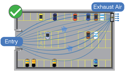 Preferred natural air path
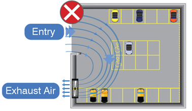 Natural air path to be avoided
- For ‘Linear Flow Systems’, supply and exhaust points should be spaced across the length of a car park.
- ‘Circular Mixing Systems’ are more tolerant of closely placed supply and exhaust points, but it is advisable to have a good amount of separation.
- Supply air points should include access ramps to outside.
- The ventilation system layout should complement the natural air path from supply to exhaust points.
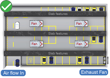 Fan’s air movement parallel to beams is most effective
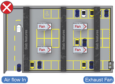 Fan’s air movement perpendicular to beams is less effective
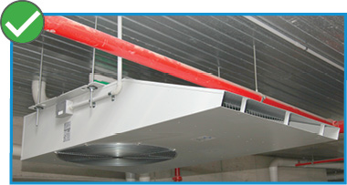
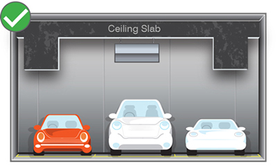 Sufficient clearance
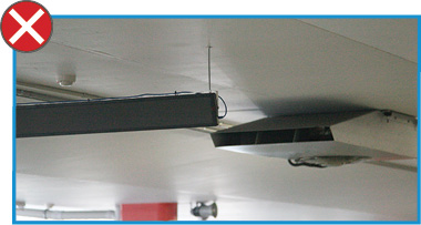
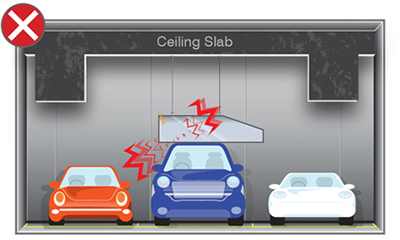 Insufficient clearance
 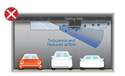 Obstruction too close
 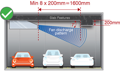 Obstruction out of the way
 An example of how to avoid clashes with pipe-work
 Signs can impede fan throw
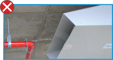 Pipework can impede fan throw
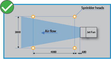 Jet fan layout in relation to sprinkler heads
This table shows the maximum and recommended spacings between JetVent Fans for different levels of fan thrust. These spacing distances are guidelines for fans placed in series. When using these spacings, air velocities in most of the ventilated areas should be greater than 1m/s. AFCD analysis will determine whether this is achieved in a particular car park design. In some ideal cases, designs using the maximum distances have been effective.
Fan thrust depends on the operating speed of a particular fan unit and its thrust rating.
Select the EC JetVent fan model based on their recommended spacing/ coverage and the space needing to be ventilated.
| Operating Fan Thrust | Operating Fan Thrust | Recommended Fan Spacing* | Maximum Fan Spacing | Recommended Coverage* |
|---|---|---|---|---|
| 48.2N | 50m | 60m | 1000m2 | JIU-CPCEC-HP |
| 36.5N | 35m | 46m | 730m2 | JIU-CPCEC-USD |
| 28.4N | 30m | 40m | 560m2 | JIU-CPCEC-SD |
| 18.9N | 25m | 33m | 730m2 | JIU-CPCEC-LH |
| 23.0N | 20m | 27m | 350m2 | JIU-CPCEC-ULH |
Select Isolator and Smoke Detection Kit
ISOLATOR KIT
HP, USD, SD, LH JetVent Models
Code: JIU-ISOLATORKIT
SMOKE DETECTOR KIT
HP, USD, SD, LH JetVent Models
Code: JIU-SMOKEKIT
ULH JetVent Model
Code: JIU-SMOKEKIT-ULH
After a preliminary fan layout is completed using the spacing distances above, the layout may be checked for total installed thrust. Successful designs typically have approximately 5N of thrust per 100m2 of car park floor area. This thrust ratio also works well for estimating purposes.
Note that using higher rated JetVent fans generally makes the system more cost effective than using more lower rated fans. This is due to the requirement of less JetVent fans and hence saving on capital costs, installation costs and running costs. However, to effectively ventilate car parks with low ceiling heights, unusual or irregularly geometries, selecting more fans with smaller thrust ratings may be necessary.
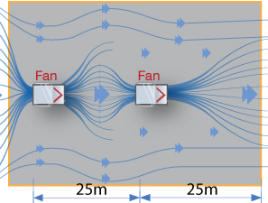 Two 25N fans
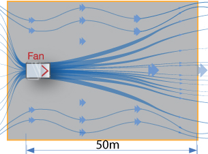 One 50N fan
 Fan sizing and placement example
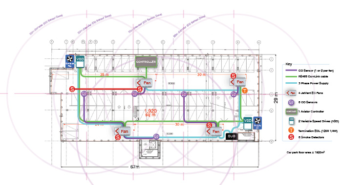
- Based on 5N per 100m2 floor area,
minimum total fan thrust = car park floor area x 5N/100m2
= 1920m2 x 5N/100m2
= 96N - Minimum thrust criteria can be achieved with 4 x JIU-CPCEC-SD fans on preset speed (operating thrust 28.4N), total fan thrust = 28.4N x 4= 113.6N.
- Fans are spaced within the 35m spacing recommendation for thrust levels.
- Final fan to wall spacing under 40m maximum spacing guide lines for fan thrust. This is because the exhaust point is an area of low pressure, making it likely to enhance the fan throw distance.
ComLink Design Parameters
Aviator controls should be placed in the Mechanical Services Switchboard enclosure. The RS485 ComLink line must start at the controller and then daisy chain to all the JetVent Fans and Drives. The last connection must have an End-of-Line resistor. If the line is greater than 1,000m or includes more than 32 connected devices, then a communications repeater must be added to extend the line. A repeater can also be used where the ComLink line branches off, such as at the beginning of each level in a multi-story car park.
Fantech can provide support for electrical cabling mark-up designs, to help ensure the most efficient ComLink strategy is used.
Because the guidelines for positioning CO sensors in AS/NZS1668.2:2012 is based on a ducted system, we propose that the following guidelines be used as a starting point for their placement in a jet fan system.
- No part of the enclosure shall be greater than 25 metres from a sampling point. (A 50 metre diameter circle around a CO sensor can show coverage areas).
- Additional detectors shall be installed in areas where people may congregate within the car park and are not within separately ventilated areas.
- The most practical mounting position for a CO sensor within a car park is the support columns.
- CO sensors will be more effective if placed in areas where CO levels are likely to be high. Eg. Placing a CO sensor in front of a fresh air intake is not likely to be effective.
Aviator controls should be placed in the Mechanical Services Switchboard enclosure. The RS485 ComLink line must start at the controller and then daisy chain to all the JetVent Fans and Drives. The last connection must have an End-of-Line resistor. If the line is greater than 1,000m or includes more than 32 connected devices, then a communications repeater must be added to extend the line. A repeater can also be used where the ComLink line branches off, such as at the beginning of each level in a multi-story car park.
Fantech can provide support for electrical cabling mark-up designs, to help ensure the most efficient ComLink strategy is used.
| Car parks with more than 40 spaces | Car parks with less than or equal to 40 spaces |
|---|---|
| a) 2000 x F x T (minimum air quantity for one operating car) | a) 2000 |
| b) 0.85 x P x (100 x n1+ n1 x d1 + n2 x d2 ) x E x T | b) 2.5 x A |
| c) 2.5 x A (minimum air quality based on area of car park) | c) 400 n1 x P |
A = the area of the zone or level, in square metres
d1 = the average driving distance, in metres, within the zone or level under consideration for the exit of a car parked there (see Clause 4.4.4.1)
d2 = the average driving distance, in metres, within the zone or level under consideration for the exit of a car whose exit route passes through the zone or level under consideration, but excluding any part of the exit route designated as queuing areas and ventilated in accordance with Clause 4.6 (see Clause 4.4.4.1)
E = the staff exposure factor (E)
F = the staff usage factor (F)
n1 = the number of parking spaces in the zone of level under consideration (see Clause 4.3.2)
n2 = the number of parking spaces situated in other parts of the car park, having exit routes passing through the zone or level under consideration
P = the parking usage factor (P)
T = the vehicle type factor (T)
If the car park has significant queuing areas for vehicles, refer to section 4.6 in AS1668.2:2012